|
ME 405 Portfolio
|


|
|
ME 405 Portfolio
|
|
In this lab we finished development of our term project.
The objective of the assignment was to balance a 2cm diameter rubber mouse ball on a two axis tilting platform. The assembly consisted of the tilting platform, reisistive touch panel (atop the platoform) and two DC motors on the assembly's base. The system was controlled by a Nucleo-L476RG flashed with MicroPython and connected to a custom PCB boot designed by Charlie Refvem of Cal Poly's Mechanical Engineering Department. The documentation for this lab is divided into the following sections:
The actual lab was completed in multiple files. They all contain classes that work in conjunction. Once all of them are flashed to the pyb, all the user has to do is run the Lab9.py file as main and the system should balance itself. Those files include comboDriver.py, encoderDriver.py , motorDriver.py (these last two links work work when I show the html output from doxygen, but not when push them to online. They are named the same thing, so I just do not know what the problem could be), touchDriver.py, and Lab9.py. The source codes can be found on bitbucket as well at comboDriver.py -> https://bitbucket.org/dhmorse/mechatronics_shared/src/master/Lab09/HM/comboDriver.py encoderDriver.py -> https://bitbucket.org/dhmorse/mechatronics_shared/src/master/Lab09/HM/encoderDriver.py motorDriver.py -> https://bitbucket.org/dhmorse/mechatronics_shared/src/master/Lab09/HM/motorDriver.py touchDriver.py -> https://bitbucket.org/dhmorse/mechatronics_shared/src/master/Lab09/HM/touchDriver.py Lab9.py -> https://bitbucket.org/dhmorse/mechatronics_shared/src/master/Lab09/HM/main.py
To balance the ball its position and velocity must be found in addition to the angle and angular speed of the platform. The postion and are determined using the resistive touch panel. The position is found by scanning the x and y-axes of the touch panel using the driver developed in Lab07 (touchDriver.py) Velocity is then determined by comparing the change in position of the ball between two readings with respect to time. The angle and angular position of the platform were not measured in this iteration of the project, but in future iterations will be determined using an IMU. Measurements from the onboard accelerometer compared with the know vertical acceleration of gravity would provide the platform tilt angle. Meanwhile, the integrated gyroscope would provide angular acceleration values.
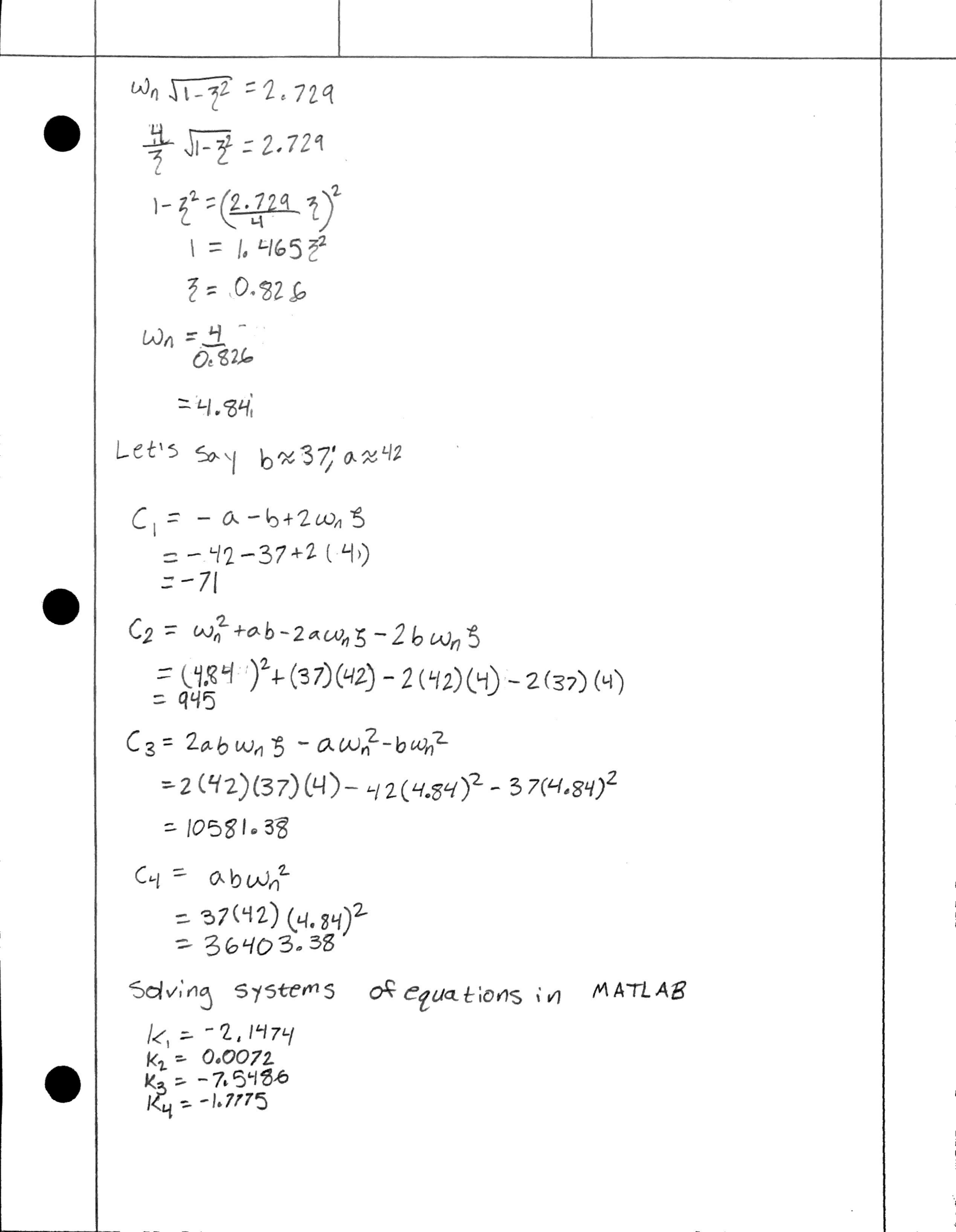
Measured values are then used to find the motor torques required to balance the ball. Torques are determined by multiplying the measured values by calculated motor gains. The torques for each motor are then converted to a duty cycle value which is used to move the motors appropriately. The calculations for the gains can be found in Gain Calculations: .
The best results we got was from the method that we probably should have started with to begin with. This method involved determining the angle and angular acceleration of the table from the encoder position. We did this by dividing the position (and speed) by 255 (counts in a full rotation), which gave us the percentage of the circle that the motor had moved. By multiplying that percentage of the circle by 2pi, we could get how many radians the motor was displaced by. From there we could multiply the length of the motor arm by sine of that angle to get the vertical displacement at the end of the rod. That displacement was also the change in height of the edge of the table because we assume that the push rod stayed vertical. From there it was a simple matter of taking the arcsine of that vertical displacement divided by the length from the center of the table to the edge, which produced the angle of the table. The same could be done with the change in encoder position to get the change in table angle. We then multiplied each of these results by the gain value calculated. Because our touchscreens did not work, we were unable to balance the ball on the table as we had hoped. If we were able to do so, the process would be similar to that of the angles. With the touch screen implemented, we would be able to easily tell the ball's position. By consistantly updating our position the screen, we would be able to obtain the change in position with respect to time, giving us the speed of the ball. We could then multiply those by the gains we computed. Once that was done, we could sum up all of those torques, from the angle, position, angular velocity, and velocity, multiply by the motor resistance and 100% and divide by the power supply voltage and the torque constant to get the necessary duty cycle. As it is, we could only compute the duty cycle without the torques produced from the linear speed and position.
https://youtu.be/_cNrHkeaciU <- FINAL RESULTS
We were unable to successfully balance the ball on the platform. We attempted the problem from a number of angles with varying methods (see The Attepmts). In following video Hunter describes the system in its current state. Hunter https://youtu.be/0fpSM2Fekm0
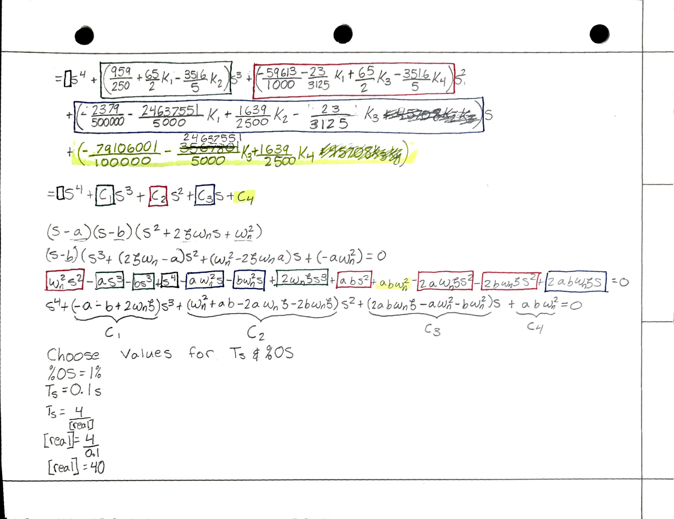
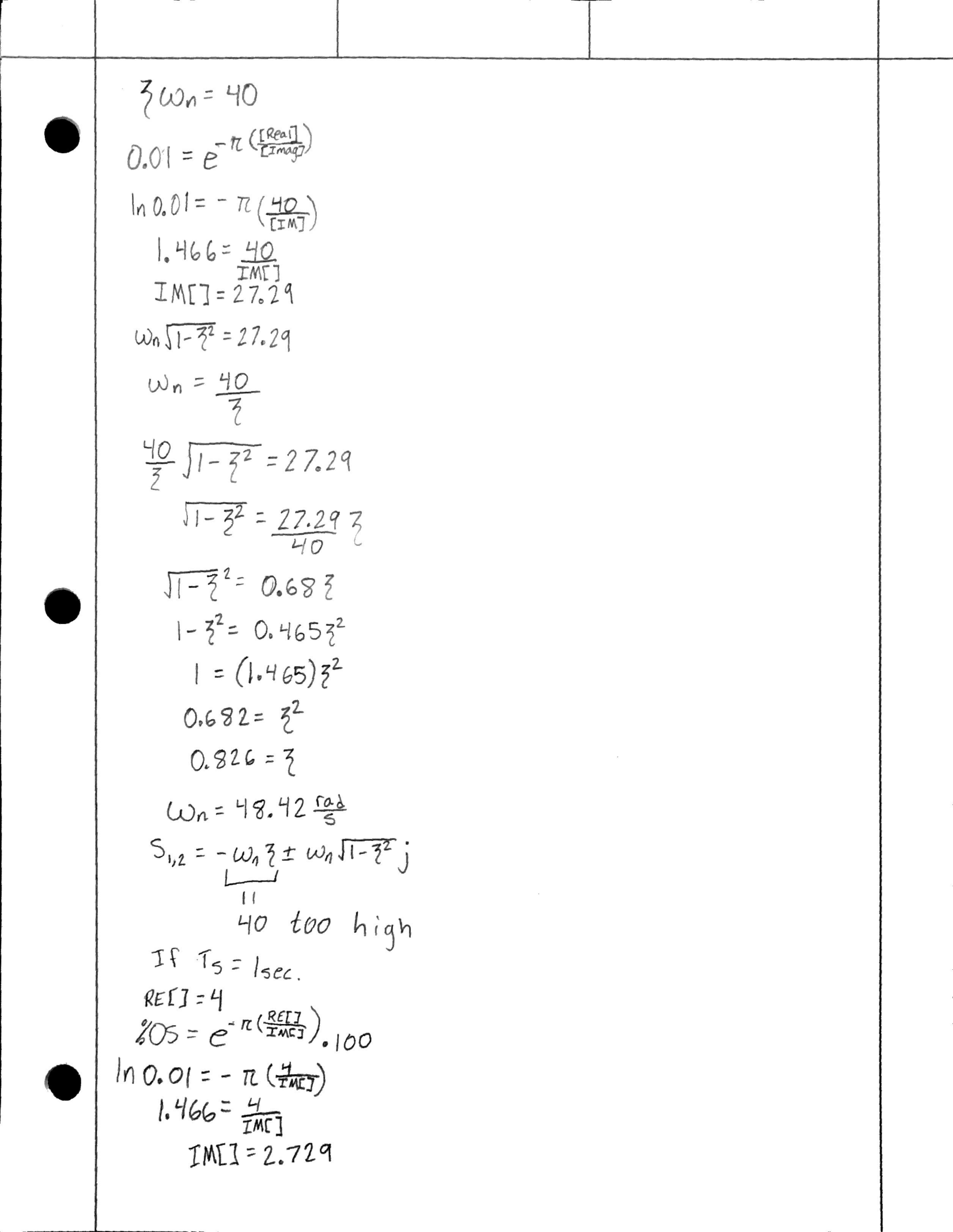
However, we are proud to say that we did end up figuring out how to do apply the gain value method that we learned in class to our project. By working through many methods that did not work because we did not fully understand what we were supposed to be doing, we were able to work our way to understanding exactly what we should have understood all along. It was a classic "learn by doing" scenario. Were we to do it again with functioning equipment we would start out applying this method and we are sure it would work much better. As far as the gains go, we learned that the ones we produced from hand calculations were far below what was actually necessary. With some tuning we could get the table to be a bit smoother than it initally was. We think this had to do with the reality of the equipment and our assumptions. We shot for a settling time of 1 second and a percent overshoot of 1%. Those were good goals to shoot for, though realistically our equipment was not capable of acheiving those goals. We probably had to amp up our gains to make up for the disparity between math and mechanical reality. Also, they turned out negative in the calculations. This was most likely due to a directional error. Jacob describes the results below. Jacob https://youtu.be/_cNrHkeaciU Apologies for how quiet the video is. It was late and I did not want to wake my roommates.
Original K = [-2.1474, 0.0072, -7.5486, -1.7775] Tuned K = [NotApplicable, 1.3, NotApplicable, 8.2]
Five such attempts are included in our source files. It is recommended to view them in the order they were attempted as the doxygen descriptions each attempt references previous versions. The fifth file is a cleaner version of Attempt 3 that offers greater modularity and can more easily be run on other balancing systems.
Although unsucessful in achieving our goal by the project deadline, we made significant progress overall and gained a much deeper understanding of Micropython, motor/sensor interfacing, modeling dynamic systems, and designing controllers. Our biggest take away: this sh*t is time consuming and hard. Nevertheless it is fascinating and endlessly engaging, hence why we keep coming back for more.
If I had to restart the project from scratch, I would begin by incorperating driver separately thus minimizing the code to debug in each iteration. Having everything included at once made it difficult to find where the bugs were hiding. That was our main error with mainWithnFault.py. Finishing this project on time was also extremely difficult given my schedule during the tail end of the quarter. Now that the quarter is over, I plan to spend Spring Break debugging and completing the project.
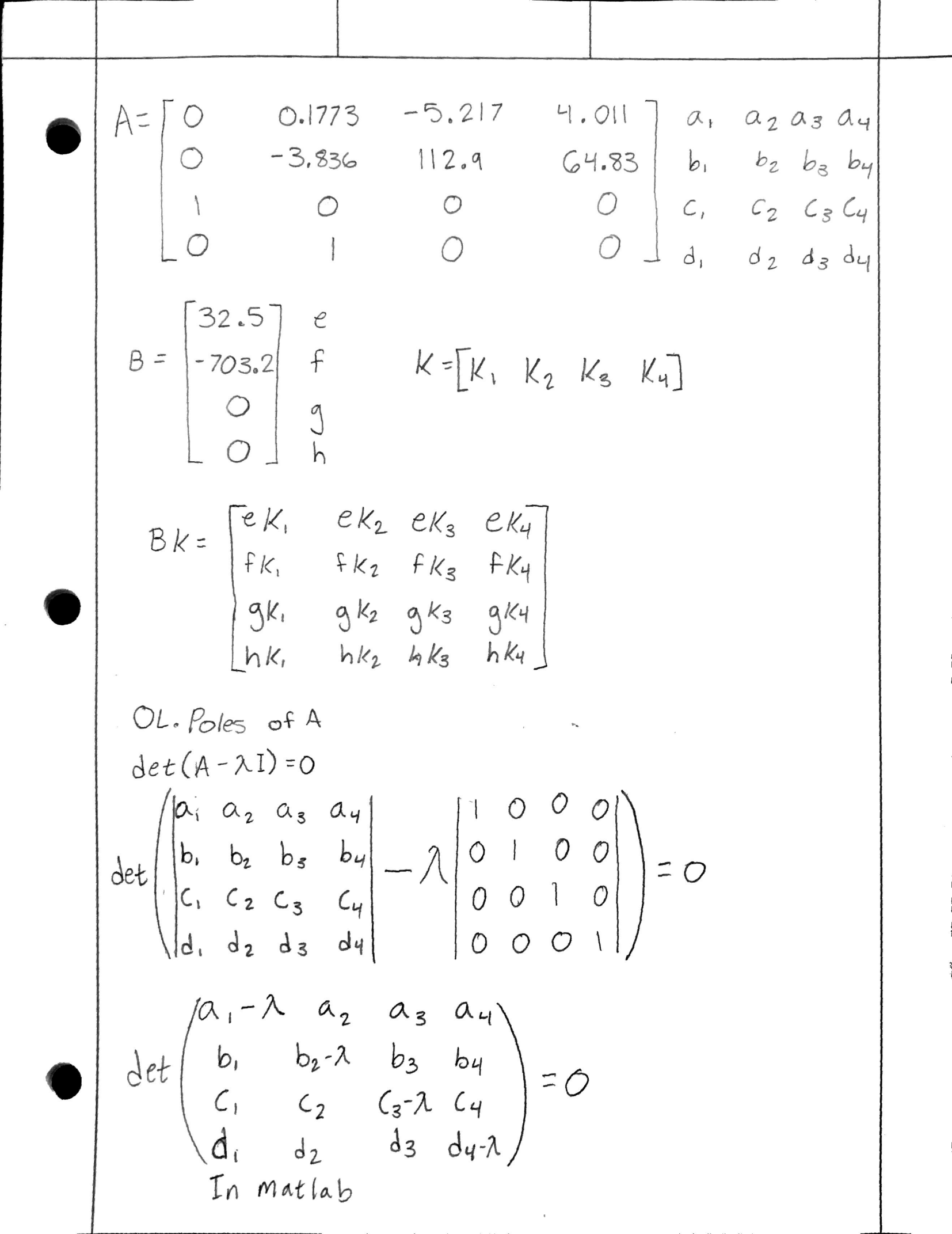
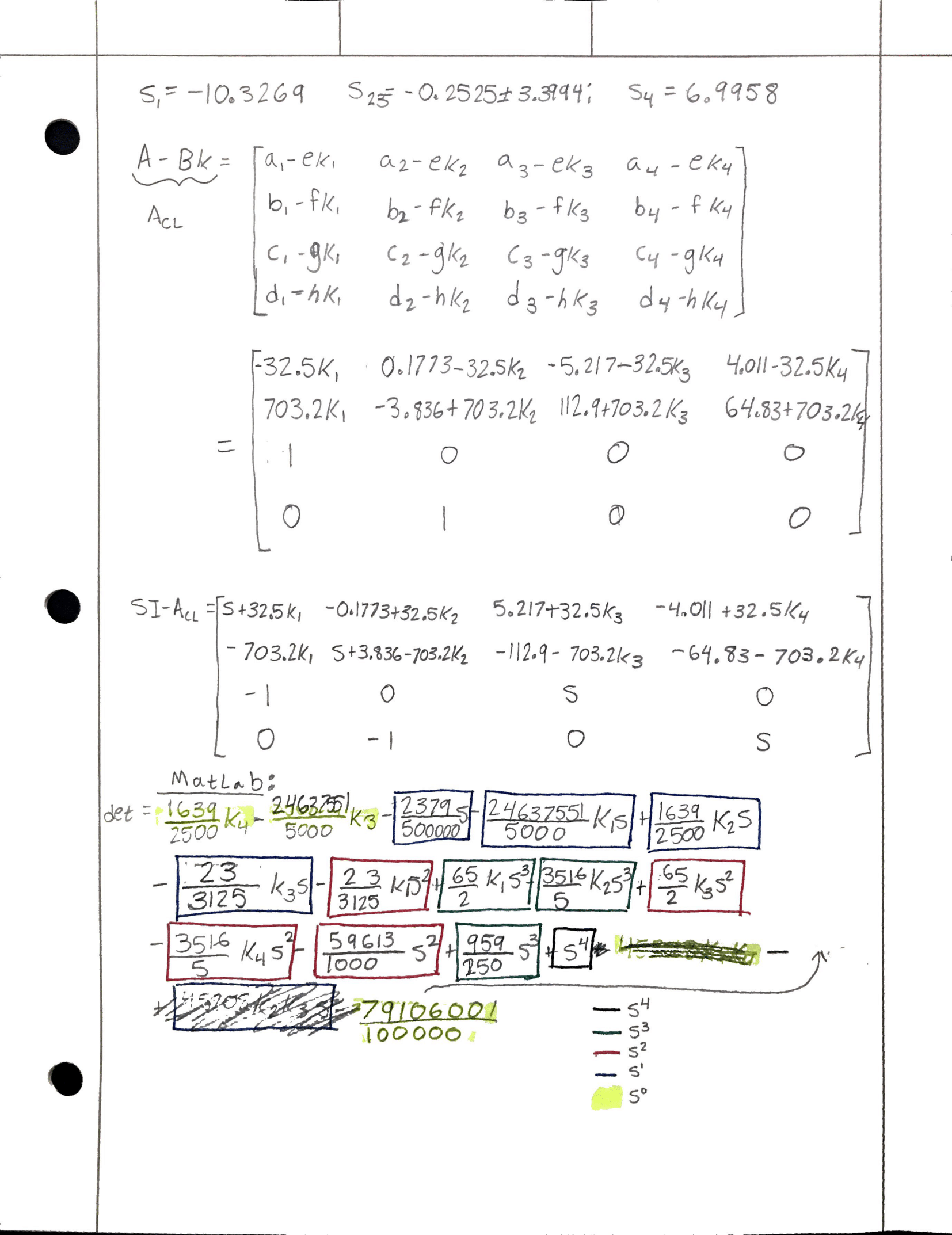
Calculations for the gains done mostly by hand, some parts in MATLAB